|
|
|
|
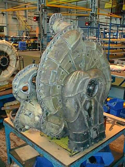
This view shows the outer casing of the scavenge-blower during its overhaul. The end nearest the camera would normally be hidden by the exhaust collector drum which would be fixed in front of this end of the blower. The blower had to be dismantled for inspection and rectification after foam from the fire brigade contaminated the blower's main bearing...
|
|
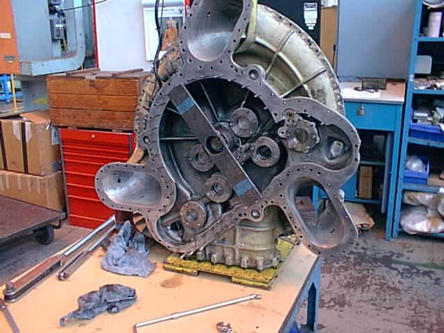
The other side of the scavenge-blower assembly is seen here. In the centre of the blower the impeller will be attached and this casing bolted to the other half of the blower which is shown in the picture below...
|
|
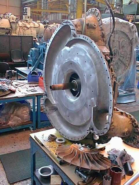
The other part of the scavenge-blower is seen in this shot. This bolts to the assembly seen in the above two shots to make up the complete scavenge-blower. In the foreground, lying on the bench is the scavenge-blower impeller which is the heart of the blower. It is when the main bearing for the scavenge-blower fails that this impeller can catch on the blower casing and disintegrate. When this happens, particles of metal can then contaminate the rest of the power unit and cause a massive engine failure, hence the importance of trying not to let the main bearing fail, by the using the correct engine oil...
|
|
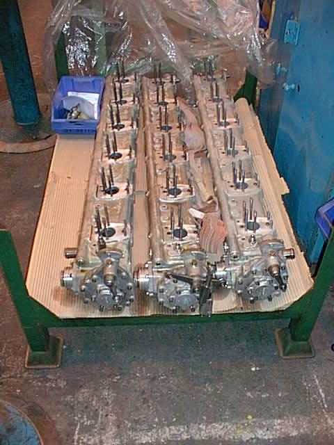
The three overhauled camboxes await fitting to the rebuilt power unit. These have been stripped and cleaned up, and now only await the fuel pumps to return from checking and calibration...
1873 - Photo: MAN B&W Paxman & courtesy of Michael Timms.
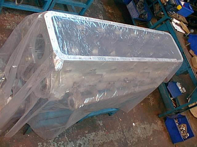
Another of the overhauled crankcases waits to be re-assembled into the triangle of the Deltic power unit for 9016. Having been thoroughly cleaned, it is covered with plastic to ensure that no particles can contaminate it before it is re-fitted to the power unit...
|
|
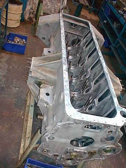
This is the bottom crankcase for 9016's power unit, the one that is rarely seen as the power unit is standing on top of this crankcase when fitted inside the locomotive. The three crankcases cannot be fitted to the power unit until the three engine blocks containing the cylinder liners have been bolted back together to make the basic triangle.