|
|
|
|
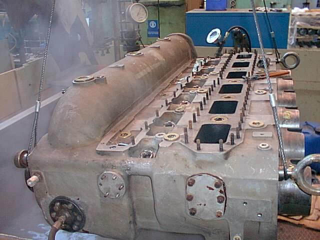
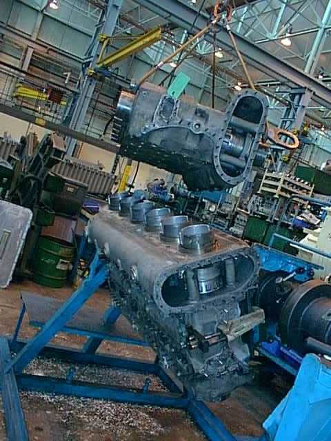
One of the completed engine blocks is held on a stand at Paxmans for pressure testing after the re-fitting of the cylinder liners. The liners in this shot can be seen protruding from the right hand side of the engine block...
|
|
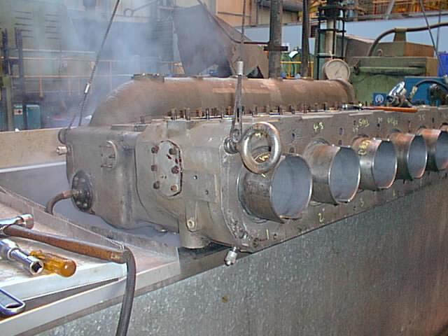
Another shot of the same engine block shows a better view of the re-fitted cylinder liners. The block is being pressure tested to ensure that coolant will not be able to enter the liners or escape from the engine block itself. Once these tests have been completed it is then possible to certify the block as fit to be re-fitted into the heart of the power unit...
|
|
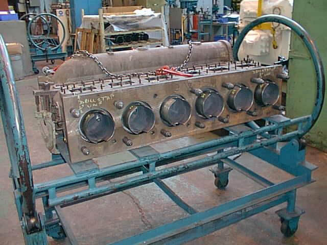
Another engine block is seen sitting on one of the turning stands at Paxman's works at Colchester. The re-honed cylinder liners can clearly be seen in this shot. Apart from pressure testing, the engine blocks also have to be dimensionally inspected to ensure that they are still to the correct dimensions and will fit together properly when re-assembly takes place...
|
|
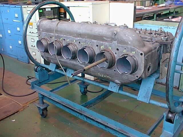
Part of the dimensional testing equipment is seen in place in one of the cylinder liners in the completed engine block. Once the three engine blocks have been re-assembled into a triangle, the crankcases can be added to them, and then the moving part such as con-rods, pistons and crankshafts can also be re-fitted...
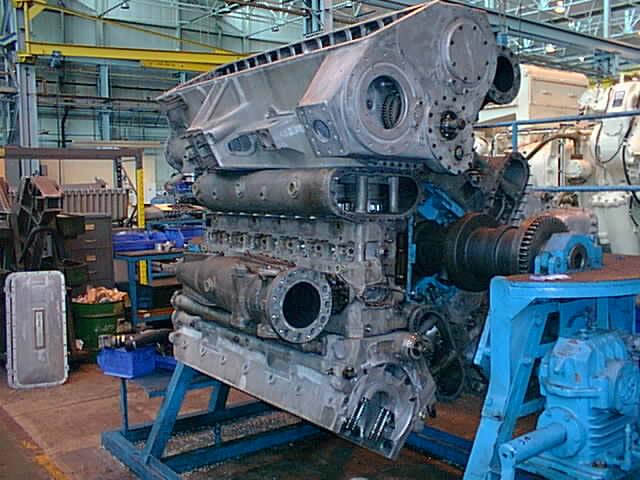
1880 - Photo: MAN B&W Paxman & courtesy of Michael Timms.Two of he completed engine blocks are seen at MAN B&W Paxman's works at Colchester during the re-assembly of 9016's power unit. The cylinder liner have all been honed out, and have now been refitted inside the engine blocks. These are then bolted together to form up the basic triangle of the Deltic engine...
|
|
This view of 9016's power unit shows the basic triangle held in one of the special turning jigs that are used to rotate the basic unit to any convenient position to work on its re-assembly. This end of the unit is the one that will be fitted to the scavenge blower. All three crankcases are back in place on the cylinder blocks, and the cylinder liners back in the cylinder blocks. The crankcase at the top of this picture is actually the bottom one of the power unit triangle in its normal position in the locomotive. Note in the background of this picture, the crankcase covers for a 9-cylinder military version of the Deltic power unit...
|
|
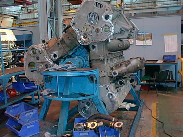
This view, taken from the other end of 9016's power unit, shows the end of the triangle that will be re-attached to the phasing gearcase of the unit. This is also the end where the main generator is situated. The basic triangle can be clearly seen in this shot, together with the holes in the crankcases where the crankshafts protrude to attach to the phasing gearcase. Towards the right of the picture can be seen one of the exhaust manifolds which leads to the other end of the unit where the collector drum will eventually be situated.